Description
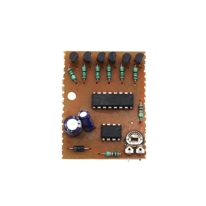
6 channel LED chaser with adjustable speed pack of 5pcs
The foundation of a 6 channel LED chaser is LED flashing. This circuit is recommended as the initial step in building a 6 LED chaser circuit. It employs IC-4017, a widely used, low-cost decade counter, and IC-555. LEDs light up one by one for a predetermined amount of time when the circuit is powered on. This indicates that LED Q1 lights up first, followed by Q2 and Q1 turning OFF, Q3 and Q2 turning OFF, and so on. The speed of the LEDs increases when the resistance of the variable resistor is changed. The trigger pin of the counter is directly connected to the increasing frequency signal caused by the 555 timer. Thus, the counter modifies its state more quickly.
ADDITIONAL INFORMATION
- Full documentation, includes Circuit diagrams, Testing document, PCB Specifications, Reading Material etc.
- Documentation will be provided on email
- Power Source: We will not provide any Battery with all the kits as they are not allowed in the shipments by Air.
PRODUCT SPECIFICATIONS:
- Led chaser circuit with 6 led outputs.
- Variable frequency.
- Best for making electronic projects.
- Ideal for making led dice project.
How does it work? The 6 channel light chaser circuit works with the two ICs, 4017 and 555 timer IC. the 555 timer IC sends a clock pulse ( or signal ) to the 4017 counter IC. The counter IC counts and sends a signal to the next output pins. There are a total of 16 pins in the 4017 IC, out of them, 10 pins are output pins. When it completes 10 counting’s, it again counts from the 1st pin.


Reviews
There are no reviews yet.